.
Tech Tip – Grid Set Issues
We are going to start off the year talking about grid set issues common to our industry and provide insights as to how to make your grid set swap seamless, quick, and less likely to have issues at start up.
If you are looking for a more advanced guide for your grid install or refurbishment, we encourage you to review “Appendix A” in our RF ion source manual. It will provide a more detailed refurbishment and installation process to follow.
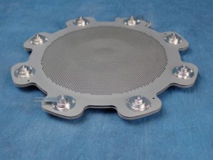
Grids and mount hardware
Brand new grids are installed less frequently than rebuilt grid sets. However, for those that operate more than one system and swap grid assemblies regularly, it can be difficult when rushed to get both new and used grids to run correctly at startup.
Whether rebuilt or new, if you follow our recommended process for grid cleaning, assembly, and installation into the mount hardware. You will reduce source operation failures during and after source startup.
New and old molybdenum grid sets
Looking at your grid set carefully before installing them in the mount hardware is important. When we build new grids, they will arrive at your facility with all spacing and testing completed and meet all requirements for operation.
If you refurbish your older grids, try to identify any obvious spacing issues, defects, and poor assembly practices. If they look good and pass all of the standard testing found in our manual, install them in the mount hardware and verify that the grids are not compressed.
The mount plate skirt should only just make contact or have a few thousandths of an inch or less gap between it at the decelerator grid.
This should be the case for the screen grid to grid retainer ring as well. Any more gap than this can cause plasma leaks and coat insulators. It can eventually cause shorts by coating the ceramic insulators in the mount assembly hardware stack.
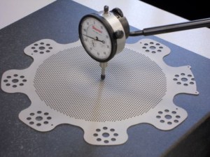
Is your grid set compressed?
Monitor compression while installing the grids in your mount hardware by using a micrometer. Measure the gap between the screen grid and accelerator before and after tightening your grid mount hardware stacks.
Did the height of your grids decrease during assembly? Check the assembly drawing and verify spacers used in your mount hardware stacks are correct and in the right location.
If you compress the grids, they cannot expand normally during warm up and may cause contact or spacing changes between grids. This can create an electrical short during process. Sadly, this can happen even after the grids start up and appear to be running well for the first thirty minutes.
Even if they do not physically short out, they can still create excessive arcing from spacing changes between the grids when compressed. This can also cause significant and uneven grid erosion.
Examine the edges of your grid assembly before and after they are installed in your mount hardware. The ears of each grid should have the same spacing all the way around the grid assembly.
When two grid ears are touching or close to one another, there may be a problem with grid warpage, compression, or a missing spacer in the grid stack.
Pre-installation testing
Those that have rebuilt grids before, know the process of testing for a short circuit between each grid. We use a “High Pot” tester that subjects two grids to a brief high voltage pulse to identify any arcs or electrical shorts.
The high pot tester generates a 1000-volt spike between the two grids being evaluated. Generation of an arc will identify either that spacing is too close or there are one or more coated or conductive insulators in the grid insulator stack.
Conductive particles can also cause a failure in your grid high pot test. A simple ohm meter may not always identify these issues unless it is a complete short. If you detect a short. Blow the grids out and retest to verify no loose particles are stuck in the grids.
Grid material
Molybdenum grids are by far the most common grids used in ion beam deposition systems. The material has sufficient rigidity, material qualities and durability in what most would agree to be a harsh operating environment.
Moly grids also hold up well to abrasive cleaning on a frequent basis. On average, a 16 cm deposition source grid set will see about seven to nine grid cleanings per year with a system running eight hours a day.
Grid and source inspection
Looking for issues
For new or refurbished grids, always inspect the contacts, or spring tabs inside the source shroud. This is where the grids connect at the accelerator and screen connection points when the grid set is installed into the ion source.
Any contact surfaces that show signs of coating or discoloration should be cleaned with fine sandpaper. There should be no discoloration on contact surfaces before installation.
Verify that the flexible spring tabs on the source shroud, and the grid set are oriented/clocked properly. See our ion source manual for details on the location. If they are not correct, they can short to ground via the stainless-steel insulator cups that hold the grid set and source tabs in place.
In cases where a grid set is run at its maximum beam current for extended periods of time, the spring tabs can lose their flexibility. When this occurs, the tab may not have enough contact pressure to make an adequate connection with the opposing rigid tab.
Sometimes the spring tabs need to be reshaped by bending the tab up and away from the mounting hardware. Do not over bend them. If one or both tabs are not making good contact, the source may not start because of a weak electrical connection.
Starting your source
Is the grid set arcing?
Grid set issues can start with arcing due to water absorbed on its surface. It is the most common issue with new or rebuilt grid sets. Moly can absorb water during the cleaning process. This can mostly be removed by placing the grid under a heat lamp after cleaning.
Entrapped water with then turn to water vapor as the grids heat up causing arcing. Pumping to a good base pressure before starting the source to minimize this effect is the best way to avoid the problem.
5.0×10⁻⁷ base pressure is recommended because even at 2.5×10⁻⁶ Torr range, there can still be water entrapped in the grids. If you have chamber heaters, use them to help bake out the grids a bit faster.
No water vapor left
Start the ion source when the system base pressure is good, and let it idle, (no beam), for 15 to 30 minutes to warm up. Turn on the beam manually at 100 mA or so, and ramp up to maximum beam current, over 10 to 15 minutes.
Some arcing may be present during this period. If there is still excessive arcing, allow the source to run at idle a bit longer.
If particles or Moly contamination is an issue for your specific process, it is recommended that you perform a grid burn in run. This will condition your grids and should eliminate most if not all arcing and reduce Moly contamination.
A grid burn in is a 4-to-6-hour test run sputtering the same materials that will be used for the production process you are running. This burn in can help reduce arcing and contamination.
Running a grid set properly
Running lower accelerator voltages helps to reduce impingement and grid erosion. Select a minimized accelerator voltage by examining our standard run data on the web site, or email us for help. If the accelerator voltage is too high, it can cause the deceleration grid to erode faster and create more moly contamination to appear in your coatings.
Even while running in the best conditions possible, the grids will still degrade over time due to usage and maintenance cycles. This is normal and expected due to the nature of the grid material and your process.
Looking for damage as grid sets age
Running process
It is highly recommended to run a Moly grid set for no more than about 300 hours of process without doing a cleaning. Exceeding this time causes damage and reduces the life of the grids. For the best results, clean the grids every 250 to 300 hours of production service.
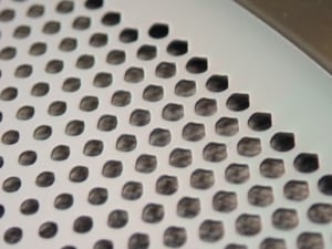
Common wear around the OD of the grids can be caused by running with a heavily coated decelerator grid that distorts the grid spacing. A distorted decelerator grid will perturb the beamlet trajectories and cause direct beam impingement. Watch for hole enlargement as you use your grids.
As grids continue to be used and rebuilt, they begin to show signs of decelerator hole enlargement. Depending on your grid set type and process parameters, this can start to show after the first year or two of use if you are treating them well.
When the decelerator hole size increases, the accelerator grid will become coating more quickly. As the accelerator grid is coated with oxide from your process, the beamlets are further perturbed and induce additional damage on the decelerator grid.
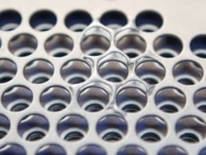
Grid set delamination
As the holes in the grid set become enlarged from use, the remaining webbing between holes becomes thinner and weaker. This allows for the layers of moly to separate much easier and this is called delamination. It usually occurs in the screen grid but may also occur on the other grids.
Long term grid set usage
If delamination does occur, it is recommended that you replace the grid set. It begins to show after media blasting a heavily used grid set or media blasting at too high of pressures.
Running grids with delamination will cause significant arcing. It is best to swap them out with a new set to reduce downtime and improve coating quality.
Grid set life in general
The average life span of a three focal point 16 cm Moly grid set used for oxide deposition is about 3 to 4 years. We have seen them last just over a year, and in other cases up to eight years. Grid set life is 100% dependent on care, operating conditions, and maintenance. Process parameters like chamber pressure, gas flows, and system geometry also play a part of the life of your grids.
12 cm Moly grids that are used for assist applications can be operated much longer compared to the 16 cm grids. Mainly because they are commonly used at lower powers and are not typically used for deposition. They are less likely to be exposed to deposition as well. This reduces the need for cleaning frequency.
Maximize grid set life and minimize production down time
Be sure to take the time to check the items we have outlined in this edition of Tech tips. Doing so will save you a lot of time in the future.
Following our guidelines should help you improve your production uptime and decrease the event of an issue with your grids and starting your ion source.
For more information about grid care, please review our Learning Center page and look under “Source Care”
Questions?
Be sure to reach out to us when you have questions. We certainly want you to be successful and maximize your equipment uptime. Let us know if there are topics you would like to see in a future Tech Tip edition!