December 2023
Special Edition
Gas flow is required in nearly all plasma process technologies. Those in the high-vacuum industry are aware that gas flow is a vital part of every process we use in the thin film industry. Ion beam deposition and ion assisted deposition require gas flow to run process. Ion beam gas flow issues can wreak havoc on any process and cost time and money. There is a lot we can learn about gas flow issues and their impact on ion beam processing. In this edition of Tech Tips, we would like to share some of our experience with gas flow and troubleshooting.
Tech Tips – Gas Flow
Ion beam gas flow
Let’s start with a basic vacuum chamber. A vacuum chamber is used to provide an environment free of gases found in the atmosphere, including water vapor. When a chamber is free of gases, it can then be used to run a controlled process with a desired gas environment. Once the chamber is evacuated and free of water vapor and atmospheric gases (i.e. achieved a base pressure in the 5×10⁻⁷ torr range) the chamber is ready to run a controlled process. This is where gas flow becomes the basis of this latest Tech Tip.
Standard gas flow
Ion beam deposition can occur in an inert or reactive gas environment. For our common 16 cm RF ion beam source, gas flow is nominally 15 to 20 sccm of argon and 4 to 5 sccm of Argon to the RF neutralizer. As a rule of thumb, the source dimension, (grid size), should be equal to the flow needed for the ion source. As an example, a 12 cm ion source should run with 12 sccm of Argon and so on. This flow rate can vary depending on the system pumping speeds. This rule also changes when using reactive gases like Oxygen and Nitrogen through the source. In which 10 to 20% more flow may be required to operate.
Ion beam Gas flow for oxides
When using Oxygen as a process gas, one of the common practices is to introduce O2 into the sputter plume between a target and the substrate to help oxidize your film. While running this process in a chamber, a 16 cm source has a flow around 18 sccms of Argon, 25 sccms of O2 to the sputter plume, (between the target and substrate), and 4 to 5 sccms of Argon to the RF neutralizer.
Process pressure and ion beam gas flow
The ion beam gas flow values above are common but can vary depending on process and pumping speed. Keeping gas flows near this range is a good starting point. Chamber pressure between 1.5×10⁻⁴ and 5.0×10⁻⁴ torr during process is standard for our ion beam equipment. Operating below this pressure range will require a higher gas flow to maintain normal ion source operation. Operating above this pressure range can cause excessive arcing, parasitic plasma issues and an E71 error. Please see our previous Tech Tip for information on this subject.
Cryo Pump, chamber pressure and gas flow
Importance of good pumping and gas flow
A common failure related to process gas flow can be pumping speed and pump efficiency. If a system is cryo pumped, while under process load, (warmed up and running process), the cryo temperature in the first stage should not exceed 75 Kelvin. Higher cryo temperature reduces pumping efficiency and will cause issues with ion source operation. This reduction in pump efficiency is like running too much gas flow in the process.
Cryo pump and operating temperatures
An efficient pump should keep a chamber base pressure at about 5×10⁻⁷ torr or lower. If it does not pump to this level within three to four hours, it is a sign of decreased pump efficiency. Once temperatures for the first stage of a cryo pump exceeds 65 Kelvin, a cryo pump will be struggling to meet the gas flow demand. It cannot meet pumping requirements necessary for the stable operation of an ion source. A regenerated pump may or may not help. When a pump still does not meet efficiency standards after regeneration, the cryo pump needs refurbishment. Normal cryo temperatures should be 12 to 15K and 65 to 73K.
Gas bottle and gas line leaks
Is my gas flow system set up correctly?
Every gas flow distribution system should use stainless steel gas lines to connect a gas bottle to the process chamber. It is also important to use five nines (99.999%) quality gas for ion beam processes. Plastic gas lines should not be used due to permeation and impurities from the plastic mixing with high-purity gas. Any plastic will directly affect RFN life and cause quality issues with some thin films.
Easy way to check gas supply for leaks
When a suspected leak is occurring in your supply line, turn the gas bottle off at the main bottle valve. Then turn on gas flow to the chamber while under vacuum. Set it to a safe but high flow rate to allow it to evacuate the lines. Evacuating gas lines completely can take 10 to 20 minutes. Once there is no gas left in the lines, your flow controller should detect less than one sccm of actual flow. If the flow rate stays higher than this for ten minutes or more, you have identified a leak in the line.
Gas line pressure
Have you identified a leak in your gas line? If so, turn off the gas flow controller and slowly repressurize the lines using your gas regulator. Gas supply pressure from the bottle should be set to a minimum of 25 PSI, (above 14.7 PSI at sea level). Once pressure of 25 PSI has been reached, gas line fittings can be checked for leaks and tightened or replaced, as necessary. Use a bottle of soapy water to help locate a leak. Simply look for the bubbles. Check your regulator fittings on your bottle as well.
Is the correct gas hooked up?
Typically, a five nines quality (99.999%) pressurized bottle connects to a system via a gas flow control system and stainless-steel gas lines. Be sure to confirm the bottle being changed on your system is the correct quality and type before installation in your system. Always double check the label. Though rare, and something to note, a brand-new bottle of gas can be installed on a system and turn out to be the wrong gas. This error has occurred twice for us. In our case the bottle was mislabeled. When in doubt, change the bottle.
Bad gas?
In some cases, the bottle that had been installed was contaminated or of a low grade. This too is rare, but it can happen. It is always good to look back when something goes wrong with the vacuum process. Off colored plasma or bad optical coatings are the first signs of a leak or a bad bottle. If your process saw dramatic changes after a bottle change, confirm it was the right gas. Did you just change your gas bottle? Have your coatings changed drastically after installing a new bottle? Confirm it is the right gas and is not contaminated by switching the bottle again.
Quality gas
It is recommended to change your gas bottle when its pressure reaches 200 PSI. They should not be run till they are empty. When changing a bottle, some mass flow controllers (MFCs) can be damaged if they are subjected to high pressure at a high rate of speed. Always turn the regulator down to zero pressure before changing the bottle.
When the new bottle is installed, turn on the main valve and ramp up pressure to the gas line slowly to avoid damage to your MFCs. Be sure that the gas system is purged after changing the gas bottle to remove atmospheric gases prior to ion source operation. This is achieved by turning on flow at a high rate to your system and flowing gas for ten minutes or more.
Is your gas flow rate accurate?
Mass flow sensors and controllers are used to control your gas flow in most high vacuum systems. Each controller should be calibrated and a correction factor is set for each specific gas being controlled. If it is not set correctly, the flow rate to the system will not be accurate. When a bottle is changed to a new gas type, it is important to change the correction factor to accommodate the new gas type. All gas flow control system manufacturers should have a list of correction factors and instructions in the operator’s manual. There, you can learn how to check and change these correction factors for the gas type being used. Some systems may simply allow you to choose the gas type and the correction factor is updated through software.
Water leak is gas flow
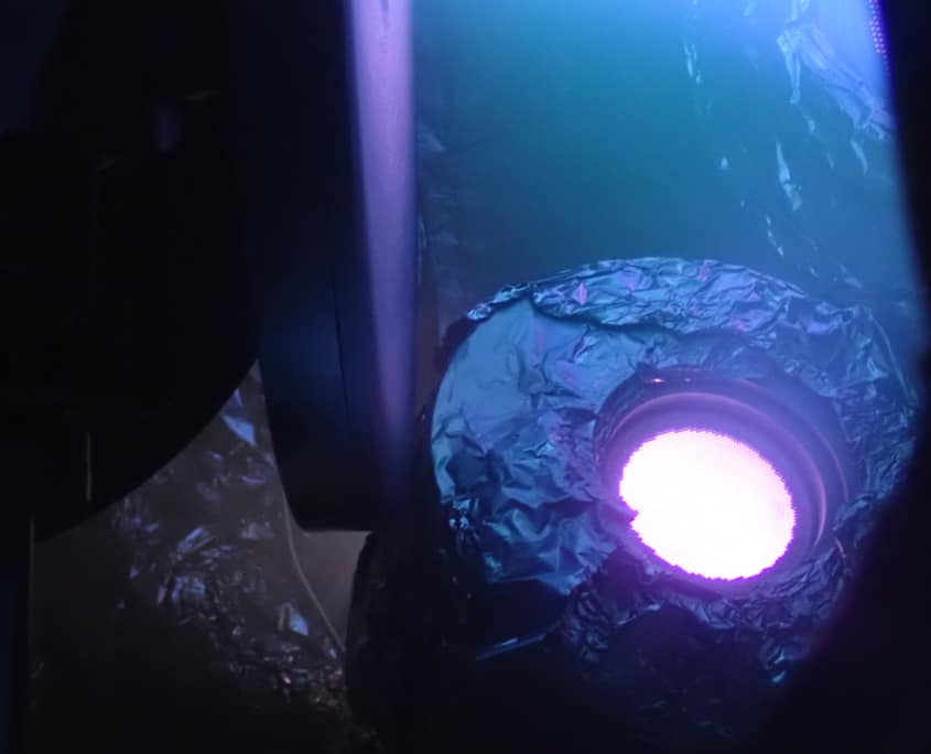
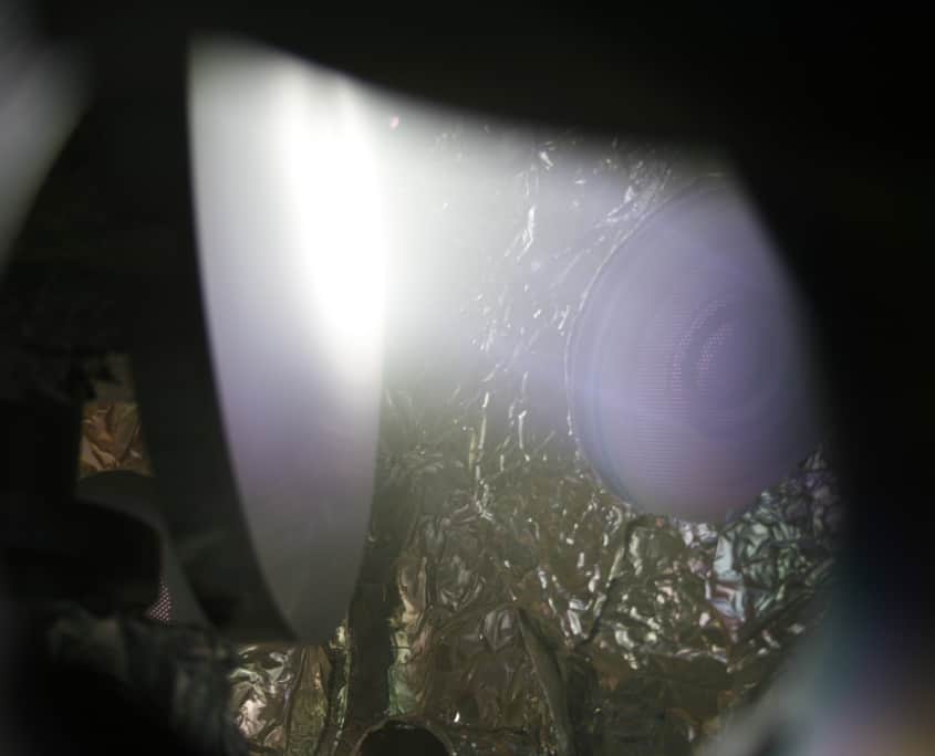
Did you know that a leak can cause a change in your plasma color? When a water leak is present, the plasma will be white in color and the most difficult to see in an Oxygen process. If you suspect a water leak, and you are running an oxide process, switching to pure argon, and running the source briefly could help determine a water leak is present. The plasma will stay white if you have a leak present. If a leak is suspected, water lines should be blown out and pressurized with helium while monitoring your chamber gases with an RGA or leak detector to identify the location of a leak. If you suspect a rotation seal leak, turn rotation on during leak testing. A leak may be cyclical based on rotational movement.
Water vapor is gas flow
Be sure to remove all water vapor from a chamber before running a thin film process. Water vapor is still in the chamber at levels that will affect thin films and ion source operation until you achieve a base pressure of 8.0×10⁻⁷ torr or better. At 2.0×10⁻⁶ torr, there is still enough water vapor to cause issues with grid operation such as grid arcing. The better the base pressure, the better the ion beam source stability and the film quality. Infrared (IR) heaters can also be used inside of the chamber to remove water vapor more efficiently.
Atmosphere leak is gas flow
When an atmosphere leak is present in a vacuum chamber, the ion source plasma will look pinkish or red due to the high nitrogen content. If you believe there is an atmosphere leak, the best way to locate it is with a leak detector or RGA and some helium. What has changed or been replaced most recently in the system? Did you just remove a flange? If so, you should start looking there. As standard practice it is always best to leak check items that have been removed and or replaced on a vacuum chamber. Even tiny leaks can have a significant impact on your process. Did you check your chamber door O-ring?
Low gas flow
Low flow rates to an ion source may not allow the source to start or it will be unstable at idle. If the ion source does start with low gas flow and the beam is turned on, the source may go out. These same symptoms will present themselves during source operation when the gas flow is turned off or the supply bottle empties.
Why won’t my source start?
Gas isolators are used to isolate the plasma in a discharge chamber from electrical ground. A leaking gas isolator or gas line can cause flow to exit into the chamber prior to reaching the ion source discharge chamber. Even though you may be flowing the right amount of gas, and your chamber pressure is normal, the ion source won’t start because the gas is not getting to the ion source. Pressure-testing the line and gas isolator is the only way to identify a leak in these areas. The feedthrough and gas isolator will need to be removed and tested for leaks.
High gas flow
High gas flow can be a much bigger issue. Too much gas flow to the source or pressure in the chamber due to decreased pumping can cause parasitic plasma and require you to refurbish the entire ion source. The E-71, or error -71, is the most common issue with ion source failures. As discussed in an earlier addition of Tech Tips, parasitic plasma is one of the most common failures that are caused by high gas flow or pressure in and around the ion source. If high pressure or gas flow is suspected as the cause of a source issue, check your pump temperatures first. Then check your chamber for leaks. Flow rate accuracy and correction factors are not as common and least likely to be the issue. However, any one of these can cause ion source operation to stop.
Questions?
Be sure to reach out to us when you have questions. We’d like to help. Bringing this in-depth segment about pumping, pressure and gas flow issues was hopefully beneficial for you and your team. We certainly want you to be successful and maximize your equipment uptime. Let us know if there are topics you would like to see in a future Tech Tip edition!


