69th Annual SVC Technical Conference • April 25 - 30, 2026
SVC Long Beach 2026 – Booth 305
read more
SPIE Photonics West in San Francisco, CA | January 20-22, 2026 | Booth 1854
THANKS TO EVERYONE WHO STOPPED BY

Optatec in Frankfurt, Germany — an international trade fair for optical technologies, components, and systems | May 5-7, 2026 | Hall 3 Booth 142
THANKS TO EVERYONE WHO STOPPED BY

We post Tech Tips, new videos, the latest product updates, plus our upcoming trade show locations so that you can chat with us in person.
Stay current with us by subscribing to our newsletter. Simply ask to subscribe by emailing us at [email protected].
69th Annual SVC Technical Conference • April 25 - 30, 2026
Techne 2e ion beam deposition system A Year of “Firsts” Wow! December already? In case you missed it, earlier this year we announced our brand-new large-area 6 x 50cm linear RF ion source. This large linear source was our first big product development...
Progress and Innovation Continues For those that have recently joined our list of ion beam enthusiasts, welcome to the newest edition of our Ion Times newsletter. If you work with ion beam, or plan to in the future, we encourage you to review some of our older...
So Much Happening This Year Spring is in the air and with two upcoming trade show events to attend in May, and with more later in the year, we are getting excited for what's to come. For our customers, we are officially releasing a brand-new product from Plasma...
Ion Beam Sputtering Video Series We are proud to announce new educational videos located in our Learning Center. These videos cover the essentials for keeping your ion beam source running smoothly. If you are new to industry, start with Lesson 1. If...
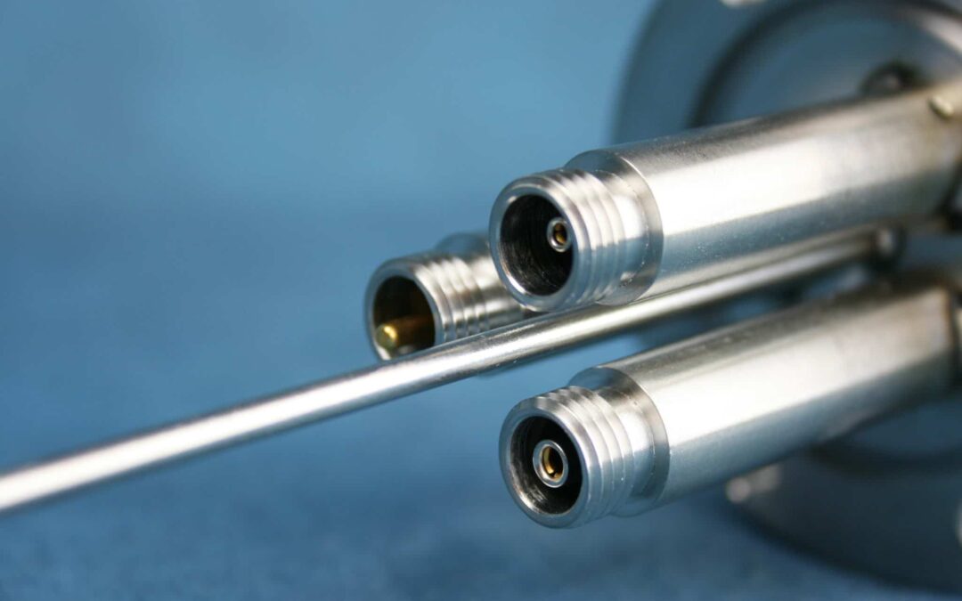
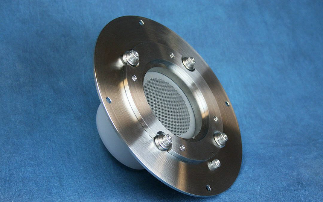
SPECIAL EDITION Feedthrough issues are the big topic for the March 2024 edition of our tech tips. However, we’d like to first send a very special “Thank you”, to everyone who stopped by our booth at the Photonics West show in San Francisco this year. It was an...
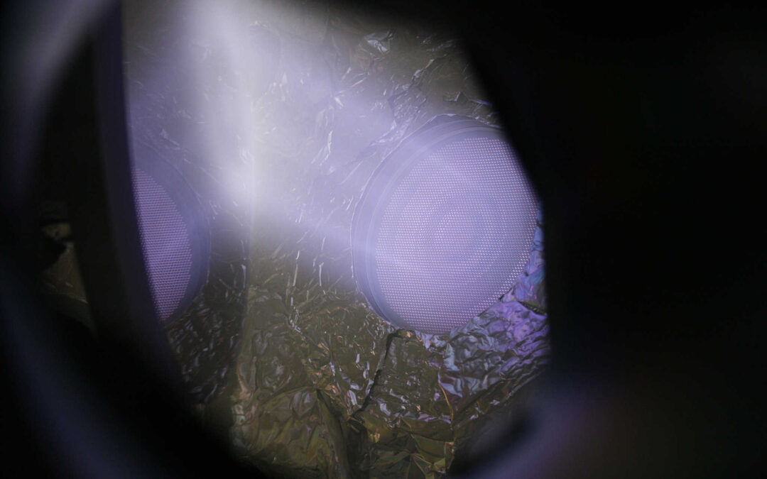
This month we are doing an in-depth look at RFN aging issues. The radio frequency neutralizer (RFN) provides the electrons each RF ion beam source requires. There is lots of useful information condensed for a quick read.
This month we are doing an in-depth look at gas flow and chamber pressure issues. Gas flow is required for the operation of an ion beam source. There is lots of useful information condensed for a quick read.
This month we are doing an in-depth look at RFN aging issues. The radio frequency neutralizer (RFN) provides the electrons each RF ion beam source requires. There is lots of useful information condensed for a quick read.
Hello from Colorado! We hope everyone has enjoyed their summer activities with their families and friends. It was a busy summer at Plasma Process Group, and we are doing our best to work toward shorter lead times for delivery of the common consumables. We owe our...
What A Show We’d like to say “thank you” to all of the folks that took the time to swing by our booth at the recent SVC TechCon show in Washington DC. It was a pleasure to see all of you there. If you did not make it to the show this year, please don’t let that stop...
69th Annual SVC Technical Conference • April 25 - 30, 2026
Techne 2e ion beam deposition system A Year of “Firsts” Wow! December already? In case you missed it, earlier this year we announced our brand-new large-area 6 x 50cm linear RF ion source. This large linear source was our first big product development...
Progress and Innovation Continues For those that have recently joined our list of ion beam enthusiasts, welcome to the newest edition of our Ion Times newsletter. If you work with ion beam, or plan to in the future, we encourage you to review some of our older...
So Much Happening This Year Spring is in the air and with two upcoming trade show events to attend in May, and with more later in the year, we are getting excited for what's to come. For our customers, we are officially releasing a brand-new product from Plasma...
Ion Beam Sputtering Video Series We are proud to announce new educational videos located in our Learning Center. These videos cover the essentials for keeping your ion beam source running smoothly. If you are new to industry, start with Lesson 1. If...
SPECIAL EDITION Feedthrough issues are the big topic for the March 2024 edition of our tech tips. However, we’d like to first send a very special “Thank you”, to everyone who stopped by our booth at the Photonics West show in San Francisco this year. It was an...
This month we are doing an in-depth look at RFN aging issues. The radio frequency neutralizer (RFN) provides the electrons each RF ion beam source requires. There is lots of useful information condensed for a quick read.
This month we are doing an in-depth look at gas flow and chamber pressure issues. Gas flow is required for the operation of an ion beam source. There is lots of useful information condensed for a quick read.
This month we are doing an in-depth look at RFN aging issues. The radio frequency neutralizer (RFN) provides the electrons each RF ion beam source requires. There is lots of useful information condensed for a quick read.
Hello from Colorado! We hope everyone has enjoyed their summer activities with their families and friends. It was a busy summer at Plasma Process Group, and we are doing our best to work toward shorter lead times for delivery of the common consumables. We owe our...
What A Show We’d like to say “thank you” to all of the folks that took the time to swing by our booth at the recent SVC TechCon show in Washington DC. It was a pleasure to see all of you there. If you did not make it to the show this year, please don’t let that stop...